SCI Sharp Controls: Phone: 704-394-1395 Fax: 704-392-5521Request a Quote!
Nachi VDS Series Vane Pump
VDS Series Small Variable Volume Vane Pump
Features
High efficiency operation with minimal power loss All the performance of the original new VDR series mechanisms combines with precision machining for a pump that minimizes power loss, especially at full cutoff.
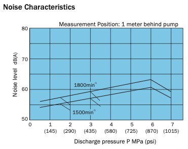
Quiet operation Journal bearings with a proven record on IP pumps plus new suction and discharge port configurations reduce operating noise and deliver quiet operation with minimal vibration, even in the high-pressure range.
Compact and simple design, easy operation Compact and quiet, VDS Series variable vane pumps are economical and easy to handle. A simple design allows use in a wide range of hydraulic systems.
Precise characteristics, prompt response Prompt response at both ON-OFF and OFF-ON ensures instantaneous, stable, high-precision operation.
Solidly built for high efficiency and long life VDS Series pumps are built to last, with a design that incorporates years of NACHI experience and know-how. Specially selected materials and skilled workmanship provide outstanding durability along with stable, high- efficiency operation.
Specifications
Model No.
Capacity in3/rev
No-load Discharge Rate gpm
Pressure Adjustment Range
psi
Allowable Peak Pressure
psi
Revolution Speed min min−1
Weight lbs
1000min−1
1200min−1
1500min−1
1800min−1
Min.
Max.
VDS-0A(B)-1A1-E11
-1A2-E11 -1A3-E11
′′ ′′
.50
2.1
2.6
3.2
3.94
145 ~ 290 317 ~ 507 435 ~ 1015
2030
800
1800
A : 14.3 B : 9.9
Handling
The direction of rotation for this pump is clockwise (rightward) when viewed from the shaft side.
Drain piping must be direct piping up to a point that is below the tank fluid level, and back pressure due to pipe resistance should not exceed 4.3 psi.
When adjusting pressure, pressure is increased by clockwise (rightward) rotation of the adjusting screw and decreased by counterclockwise (leftward) rotation.
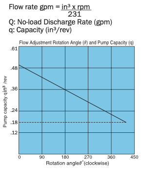
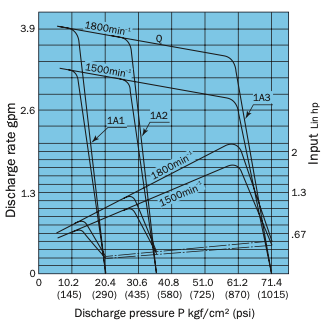
When adjusting the flow rate, the flow rate is decreased by clockwise (rightward) rotation of the adjusting screw and increased by counterclockwise (leftward) rotation. The graph on the right provides general guidelines for the relationship between the rotation angle of the flow rate adjusting screw and the noload discharge rate.
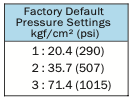
Factory Default P-Q Settings (Standard Model)
Flow Rate Setting = Maximum flow rate for model as indicated in the catalog.
Pressure Setting = Pressure shown in table below.
The values indicated above are at maximum pump discharge volume with the flow volume adjusting screwat the 0° position. The broken line shows the flow volume adjustment range lower limit value.
Thrust Screw The thrust screw is precision adjusted at the factory during assembly. Never touch the thrust screw. See callout 9 in the cross-section diagram on page B-4.
Initial Operation Before operating the pump for the first time, put the pump discharge side into the no-load state and then repeatedly start and stop the motor to bleed all air from inside the pump and the suction piping. After confirming that the pump is discharging oil, continue the no-load operation for at least 10 minutes to discharge all the air from the circuit.
For the hydraulic operating fluid, use an R&O type and wear-resistant type of ISO VG32 to 68 or equivalent (viscosity index of at least 90). Use hydraulic operating fluid that provides kinematic viscosity during operation in the range of 20 to 150 centistokes.
The operating temperature range is 59 to 140°F. When the oil temperature at startup is 59°F or less, perform a warm-up operation at low pressure until the oil temperature reaches 59°F. Use the pump in an area where the tempera- ture is within the range of 59 to 140°F.
Suction pressure is 4.35 psi, and the suction port flow rate should to greater than 6 ft/sec.
Avoid pulley, gear, and other drive systems that impart a radial or thrust load on the end of the pump shaft. Mount the pump so its pump shaft is oriented horizontally.
Provide a suction strainer with a filtering grade of about 100 μm (150 mesh). For the return line to the tank, use a 10 μm line filter.
Manage hydraulic operating fluid so contamination is maintained at class NAS10 or lower. Take care to avoid contamination with water or other foreign matter, and watch for discolor- ation. Whitish fluid indicates that air has contaminated the fluid, and brownish fluid indicates the fluid is dirty.
Contact your agent about using water- and glycol-based hydraulic operating fluids.
At startup, repeat the inching operation (start-stop) to bleed air from the pump and pipes.
Equip an air bleed valve in circuits where it is difficult to bleed air before startup. See page C-13 for more information.
To ensure proper lubrication of the pump’s rubbing surfaces, supply oil to the interior of the pump before starting operation.
When centering the pump shaft, eccentricty with the motor shaft should be no greater than 0.001 in. The angle error should be no greater than 1°.
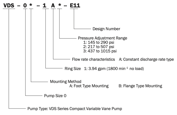
Understanding Model Numbers
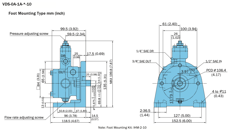
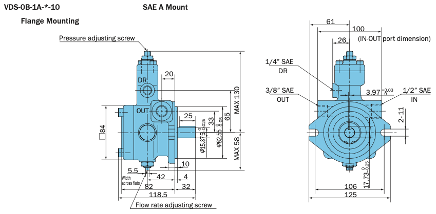
Installation Dimension Drawings
Specifications
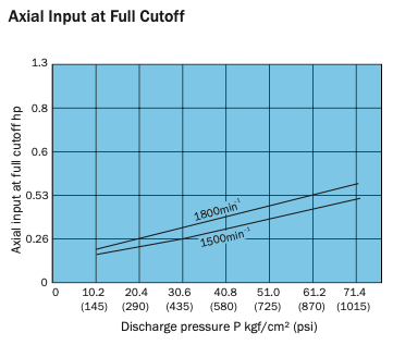
Typical characteristics at hydraulic operating fluid kinematic viscosity of 32 centistokes