Nachi VDC Series Vane pump
Features
Highly efficient and stable high-pressure operation
Innovative pressure control and pressure balance mechanisms combine with an original 3-point ring support system dramatically improves high-pressure operation. The result is outstanding performance at high pressures up to 2000 psi.
Low vibration and noise
A number of innovative new mechanisms are adopted to minimize vibration
and noise. In particular, a 3-point support system is used for the control piston and bias piston to increase ring stability. This minimizes ring vibration and delivers quiet operation.
Outstanding response, high-precision operation
An innovative new ring stopper eliminates excessive ring displacement and improves response. The result is high precision operation at all times, including during starts, stops, and load changes.
Precise characteristics for a stable discharge rate
A revolutionary new pressure compensa- tor type pressure control mechanism ensures a highly stable fixed discharge rate, even in the high pressure range.
High efficiency operation with minimal power loss
New mechanical innovations minimize power loss, especially at full cutoff.
Simplified maintenance and handling
Pressure adjusting and discharge rate adjusting mechanisms are located
on the same side of the pump for simplified maintenance and handling.
Specifications
Single Pump
Model No. | Capacity in3/rev | No-load Discharge Rate gpm | Pressure Adjustment Range kgf/cm (psi) | Allowable Peak Pressure kgf/cm (psi) | Revolution Speed min −1 | Weight lbs | |||||
Foot Mounting | Flange Mounting | 1500min−1 | 1800min−1 | Min. | Max. | ||||||
VDC-1A-1A2-*20 VDC-1A-1A3-*20 VDC-1A-1A4-*20 VDC-1A-1A5-*20 | VDC-1B-1A2-*20/35 VDC-1B-1A3-*20/35 VDC-1B-1A4-*20/35 VDC-1B-1A5-*20/35 | 1.0 | 6.6 | 7.9 | 15.3 to 35.7 (217 to 507) 20.4 to 7. 1.4 (290 to 1000) 51 to 107 (725 to 1500) 71.4 to 143 (1000 to 2000) . | 143 (2000) | 800 | 1800 | 21 | ||
214 (3000) | |||||||||||
VDC-1A-2A2-*20 VDC-1A-2A3-*20 | VDC-1B-2A2-*20/35 VDC-1B-2A3-*20/35 | 1.3 | 8.7 | 10.5 | 15.3 to 35.7 (217 to 507) 20.4 to 71.4 (290 to 1000) | 143 (2000) | 800 | 1800 | 21 | ||
VDC-2A-1A2-*20 VDC-2A-1A3-*20 VDC-2A-1A4-*20 VDC-2A-1A5-*20 | VDC-2B-1A2-*20/35 VDC-2B-1A3-*20/35 VDC-2B-1A4-*20/35 VDC-2B-1A5-*20/35 | 1.8 | 1 | 1.8 | 14.2 | 15.3 to 35.7 (217 to 507) 20.4 to 7. 1.4 (290 to 1000) 51 to 107 (725 to 1500) 71.4 to 143 (1000 to 2000) . | 143 (2000) | 800 | 1800 | 55 | |
214 (3000) | |||||||||||
VDC-2A-2A2-*20 VDC-2A-2A3-*20 | VDC-2B-2A2-*20/35 VDC-2B-2A3-*20/35 | 2.3 | 1 | 5.3 | 18.4 | 15.3 to 35.7 (217 to 507) 20.4 to 7. 1.4 (290 to 1000) | 143 (2000) | 800 | 1800 | 55 | |
VDC-3A-1A2-*20 VDC-3A-1A3-*20 VDC-3A-1A4-*20 VDC-3A-1A5-*20 | VDC-3B-1A2-*20 VDC-3B-1A3-*20 VDC-3B-1A4-*20 VDC-3B-1A5-*20 | 4.0 | 2 | 6.4 | 31.7 | 15.3 to 35.7 (217 to 507) 20.4 to 7. 1.4 (290 to 1000) 51 to 107 (725 to 1500) 71.4 to 1.43 (1000 to 2000) | 143 (2000) | 800 | 1800 | 103 | |
214 (3000) | |||||||||||
Model No. | Vent Side | Shaft Side | Revolution Speed min −1 | Weight lbs | |||||
Foot Mounting Type (Flange Mounting) | Discharge Rate gpm | Pressure Adjustment Range kgf/cm (psi) | Discharge Rate gpm | Pressure Adjustment Range kgf/cm (psi) | |||||
1800min−1 | 1500min−1 | 1800min−1 | 1500min −1 | Min. | Max. | ||||
VDC-11A(B)-2A3-2A*20/35 VDC-11A(B)-2A3-1A*20/35 | 10.5 | 8.7 | 20.4 to 71.4 (290 to 1000) | 10.5 7.9 | 8.7 6.6 | 20.4 to 71.4 (290 to 1000) 71.4 to 143 (1000 to 2000) | 800 | 1800 | Type A 59 Type B 44 |
VDC-12A(B)-2A3-2A*20/35 VDC-12A(B)-2A3-1A*20/35 VDC-12A(B)-1A5-2A*20/35 VDC-12A(B)-1A5-1A*20/35 | 10.5 | 8.7 | 20.4 to 71.4 (290 to 1000) | 18.4 14.2 18.4 14.2 | 15.3 11.8 15.3 11.8 | 20.4 to 71.4 (290 to 1000) 71.4 to 143 (1000 to 2000) 20.4 to 71.4 (290 to 1000) 71.4 to 143 (1000 to 2000) | 800 | 1800 | Type A 92 Type B 77 |
7.9 | 6.6 | 71.4 to 143 (1000 to 2000) | |||||||
VDC-22A(B)-2A3-2A*20/35 VDC-22A(B)-2A3-1A*20/35 | 18.4 | 15.3 | 20.4 to 71.4 (290 to 1000) | 18.4 17.2 | 15.3 11.8 | 20.4 to 71.4 (290 to 1000) 71.4 to 143 (1000 to 2000) | 800 | 1800 | Type A 136 Type B 110 |
VDC-13A(B)-2A3-1A*20 VDC-13A(B)-2A3-1A*20 VDC-13A(B)-1A5-1A*20 VDC-13A(B)-1A5-1A*20 | 10.5 | 8.7 | 20.4 to 71.4 (290 to 1000) | 31.7 | 26.4 | 20.4 to 71.4 (290 to 1000) 71.4 to 143 (1000 to 2000) 20.4 to 71.4 (290 to 1000) 71.4 to 143 (1000 to 2000) | 800 | 1800 | Type A 136 Type B 105 |
7.9 | 6.6 | 71.4 to 143 (1000 to 2000) | |||||||
Note:
- VDC-3A, VDC-11A, VDC-12A and VDC-13A are foot mounting types, and come with foot mountings.
- VDC-1A and VDC-2A are sub plate types. Sub plates are not included.
- Handling
- Rotation Direction The direction of rotation
is always is clockwise (rightward) when
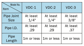
viewed from the shaft side. - Drain Drain piping must be direct piping
up to a point that is below the tank fluid level, and piping should comply with the conditions shown in the table below to ensure that back pressure due to pipe resistance does not exceed 14 psi. When using a pump that has drain ports at two locations, use the drain port that is higher after the pump is installed. In the case of a double pump, run separate pipes from both the shaft side and the head side drains directly connect to the tank, so the drain pipe is below the surface of the oil. - Discharge Volume Adjustment
The discharge flow rate is decreased by clockwise (rightward) rotation of the discharge rate adjusting screw, and increased by counterclockwise (leftward) rotation.
Loosen the lock nut before making adjustments. After adjustment is complete, re-tighten the lock nut. The graph below provides general guidelines for the relationship between the rotation angle of the flow rate adjusting screw and the no-load discharge rate.
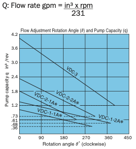
Note:
The values indicated above are at maximum pump discharge volume with the flow volume adjusting screw at the 0°position.
The broken line shows the flow volume adjustment range lower limit value.
- Pressure Adjustment Pressure is increased by clockwise (rightward) rotation of the discharge rate adjusting screw, and decreased by counterclock- wise (leftward) rotation.
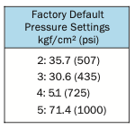
Loosen the lock nut before making adjustments. After adjustment is complete, re-tighten the lock nut. - Factory Default P-Q Settings (Standard Model)
- Flow Rate Setting = Maximum flow rate for model as indicated in the catalog
- Pressure Setting = Pressure shown in table below
- Thrust Screw and Stopper
The thrust screw and stopper are precision adjusted at the factory during assembly. Never touch them.
See callouts 15/43 and 15/38 in the VDC-1A and 2A/3A cross-section diagrams on pages B-33 and B-34. - An unload circuit is required when
the motor is started under condition WYE Delta. Contact your agent about the unload circuit. - Initial Operation
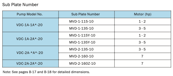
Before operating the pump for the first time, put the pump discharge side into the noload state and then repeatedly start and stop the motor to bleed all air from inside the pump and the suction piping. After confirming that the pump is discharging oil, continue the no-load operation for at least 10 minutes to discharge all the air from the circuit. Provide an air bleed valve in circuits where it is difficult to bleed air before startup. - Sub Plate
Use the table below for to specify
a sub plate type when one is
required.
- Foot Mounting
For a double pump with VDC-3 foot mounting, the foot mounting kit and pump are sold as a set. When only the mounting feet are required, pump mounting bolts, washers and other parts are sold together as the Foot Mounting Kit.
See page B-36 for detailed dimensions. - For the hydraulic operating fluid, use type ISO VG32 or equivalent (viscosity index of at least 90) for pressures of 1000 psi or lower, and type ISO VG68 or equivalent (viscosity index of at least 90) for pressures greater than 1000 psi.
- The operating temperature range is
59 to 140°F. When the oil temperature at startup is 59°F or less, perform a warm-up operation at low pressure
until the oil temperature reaches
59°F. Use the pump in an area where the temperature is within the range of 32 to 140°F. - Suction pressure is 4.35 psi, and the suction port flow rate should be no greater than 6 ft/sec.
- Avoid pulley, gear, and other drive systems that impart a radial or thrust load on the end of the pump shaft. Mount the pump so its pump shaft
is oriented horizontally. - Provide a suction strainer with a filtering grade of about 100μm (150 mesh). For the return line to the tank, use a 10μm line filter.
- Manage hydraulic operating fluid so contamination is maintained at class NAS10 or lower. Take care to avoid contamination with water and other foreign matter, and watch out for discoloration. Whitish fluid indicates that water has contaminated the fluid, and brownish fluid indicates the fluid is dirty.
- Contact your agent about using water- and glycol-based hydraulic operating fluids.
- At startup, repeat the inching operation (start-stop) to bleed air from the pump and pipes.
- Equip an air bleed valve in circuits where it is difficult to bleed air before startup. See page C-13 for more information.
- To ensure proper lubrication of the pump’s rubbing surfaces, supply oil to the interior of the pump before starting operation.
- When centering the pump shaft, eccentricity with the motor shaft should be no greater than 0.001 in. Use a pump mounting base of sufficient rigidity. The angle error should be no greater than 1°.
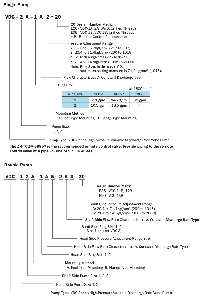
Understanding Model Numbers
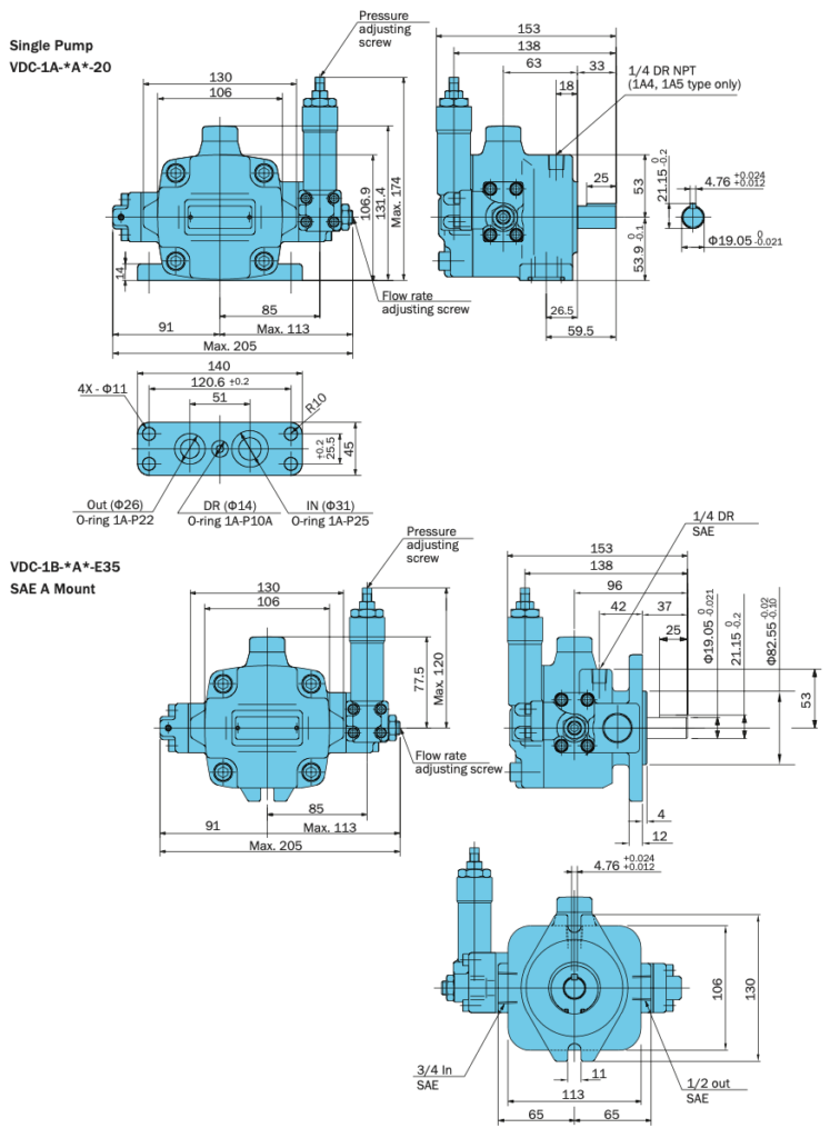
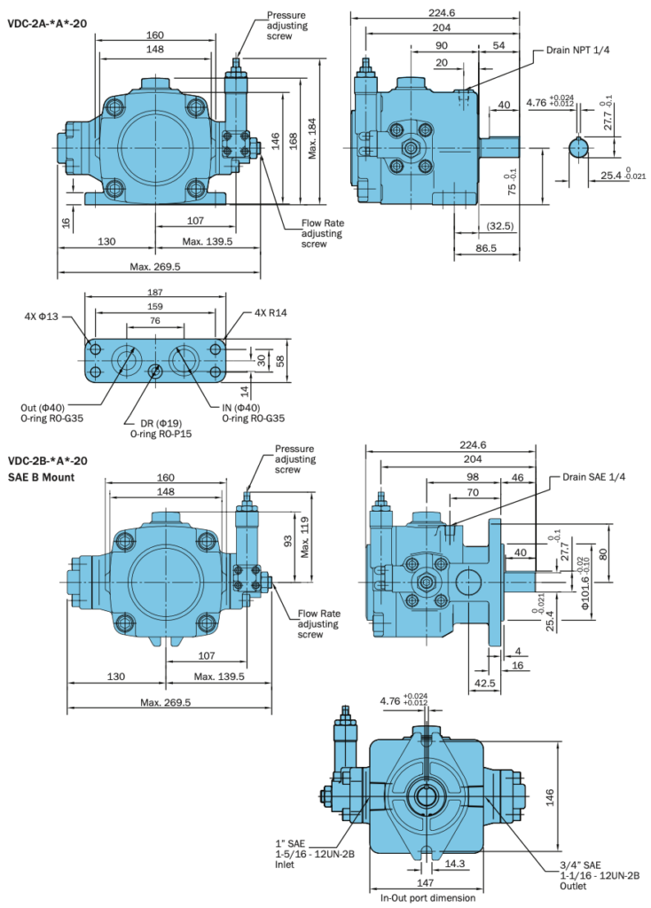
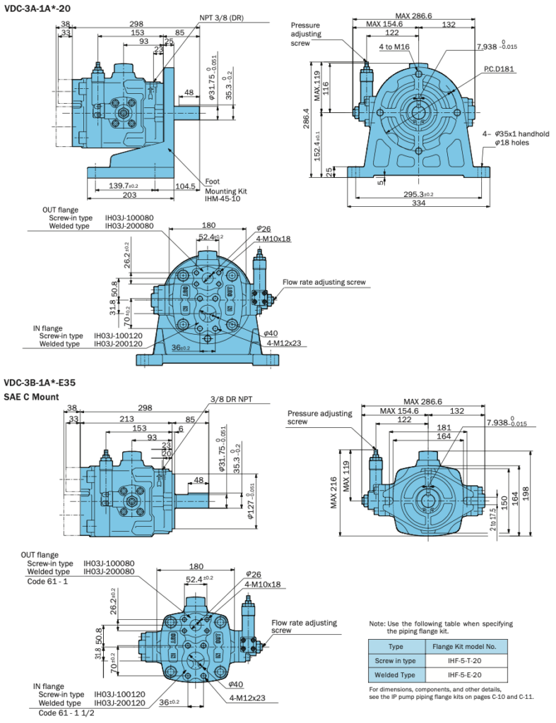
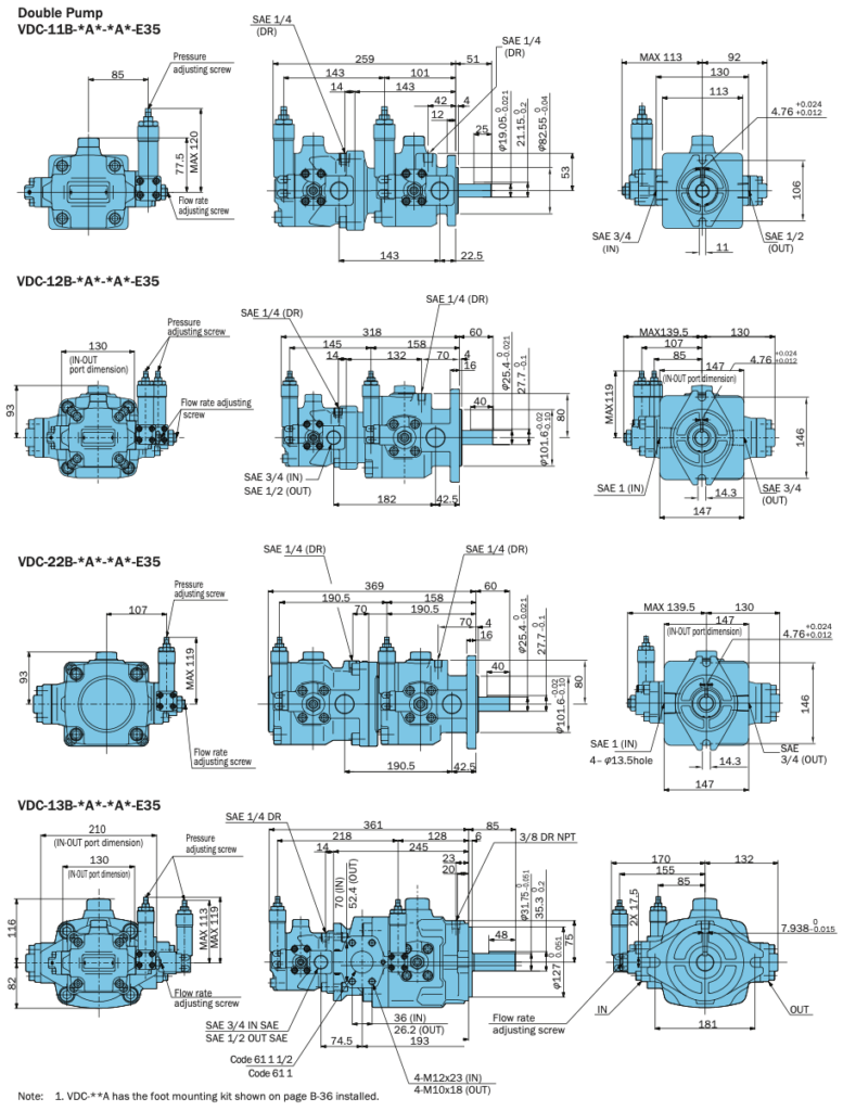
Installation Dimension Drawings
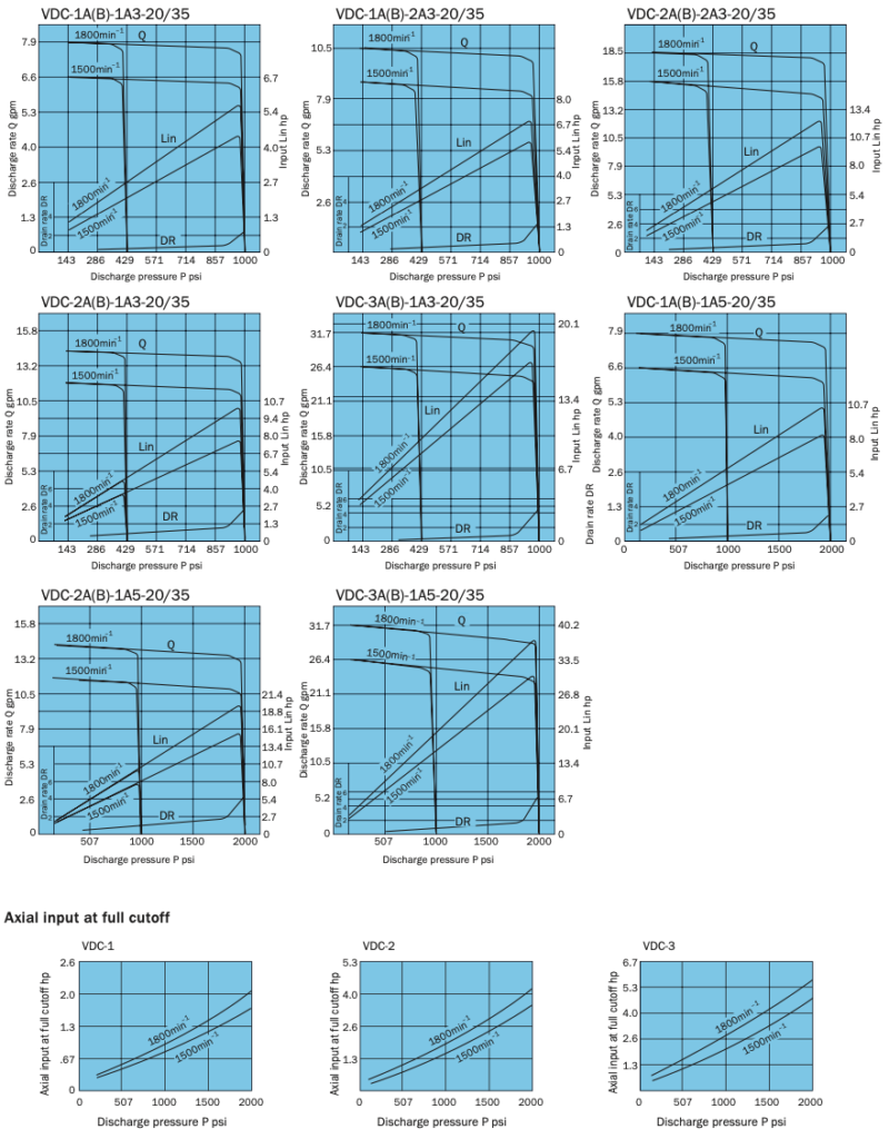
Performance Curves
We offer the above from the following Brands