SCI Sharp Controls: Phone: 704-394-1395 Fax: 704-392-5521Request a Quote!
Nachi VDR Series Vane Pump
VDR 22 Design Series Variable Volume Vane Pump
Features
Stable, highly efficient operation up to 2030 psi A biased piston that minimizes ring vibration and leak-free pressure balance construction enables highly efficient highpressure operation, and very stable performance up to 2030 psi.
High-precision instantaneous response Response has been improved by a special bias piston mechanism. Prompt response at both ON-OFF and OFF-ON ensures instantaneous, stable, high-pre- cision operation.
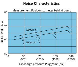
Silent operation, even in the high pressure range CQuiet journal bearings, a bias piston that allows a 3-point support system, and new suction and discharge port shapes all contribute to minimize operation noise. Silent, vibration-free operation is ensured, even in the high pressure range.
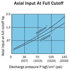
Reduced power loss A combination of NACHI-original mechanical innovations and precision machining create a pump that minimizes power loss, especially at full cutoff.
Solid construction stands up to harsh operating conditions The tough and rugged construction of this pump is made possible by a long history of quality pump designs. This, in combination with specially selected materials and skilled workmanship, provides outstanding durability.
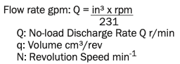
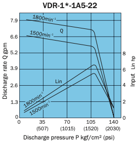
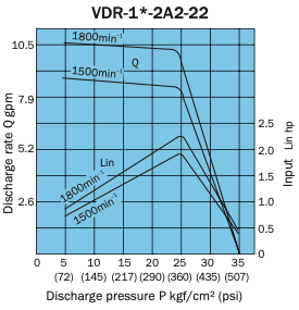
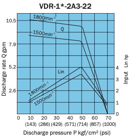
The discharge rate is the value at 1800min-1 no load.
The change from design number 21 to design number 22 represents a change in the shaft key width from .125 in to .187 in. This means that
when using a .125 in key coupling, you need to use a stepped key (VD31J-302000) or add a new key groove at .187 in.
Handling
Rotation Direction The direction of rotation is always is clockwise (rightward) when viewed from the shaft side.
Drain Drain piping must be direct piping up to a point that is below the tank fluid level, and back pressure due to pipe resistance should not exceed 4.35 psi. When using a pump that has drain ports at two locations, use the drain port that is higher after the pump is installed.
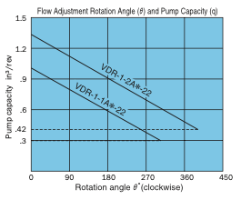
Discharge Volume Adjustment The discharge flow rate is decreased by clockwise (rightward) rotation of the discharge rate adjusting screw, and increased by counterclockwise (leftward) rotation. Loosen the lock nut before making adjustments. After adjustment is complete, re-tighten the lock nut. The graph on the right provides general guidelines for the relationship between the rotation angle of the flow rate adjusting screw and the no-load discharge rate.
The broken line shows the flow volume adjustment range lower limit value. Note: The values indicated above are at maximum discharge volume with the flow volume adjusting screw at the 0° position.
Pressure Adjustment Pressure is decreased by clockwise (rightward) rotation of the discharge rate adjusting screw, and increased by counterclockwise (leftward) rotation.
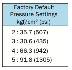
FactoryDefaultP-QSettings(Standard Model)
Flow Rate Setting = Maximum flow rate for model as indicated in the catalog
Pressure Setting = Pressure shown in table to the right
Thrust Screw The thrust screw is precision adjusted at the factory during assembly. Never touch the thrust screw. See callout 21 in the cross-section diagram on page B-11.
Initial Operation
Before operating the pump for the first time, put the pump discharge side into the no-load state and then repeatedly start and stop the motor to bleed all air from inside the pump and the suction piping. After confirming that the pump is discharg- ing oil, continue the noload operation for at least 10 minutes to discharge all the air from the circuit.
Provide an air bleed valve in circuits where it is difficult to bleed air before startup.
Sub Plate
Use the following table for specification when a sub plate is required.
For detailed dimensions, see pages B-17 through B-19.
For the hydraulic operating fluid, use type ISO VG32 or equivalent (viscosity index of at least 90) for pressures of 1015 psi or lower, and type ISO VG68 or equivalent (viscosity index of at least 90) for pressures greater than 10 15 psi.
Pump Model No.
Sub Plate Number
Motor(hp)
VDR-1A-1A*-22
MVD-1-115-10
1~2
MVD-1-135-10
3~5
VDR-1A-2A*-22
MVD-1-115Y-10
1~2
MVD-1-135Y-10
3~5
VDR-11A-*A* -*A*-22
MVD-11-135-10 MVD-11-135X-10
2~5
The operating temperature range
is 59 to 140°F. When the oil temperature at startup is 59°F or less, perform a warm-up operation at low pressure until the oil temperature reaches 59°F. Use the pump in an area where the temperature is within the range of 32 to 140°F.
Suction pressure is 4.35 psi, and the suction port flow rate should be to greater than 6 ft/sec.
Avoid pulley, gear, and other drive systems
12 that impart a radial or thrust load on the end of the pump shaft. Mount the pump so its pump shaft is oriented horizontally.
Provide a suction strainer with a filtering grade of about 100 μm (150 mesh). For the return line to the tank, use a 10μm line filter.
Manage hydraulic operating fluid so contamination is maintained at class NAS10 or lower. Take care to avoid contamination with water or other foreign matter, and watch out for discoloration. Whitish fluid indicates that air has contaminated the fluid, and brownish fluid indicates the fluid is dirty.
Contact your agent about using water-and glycol-based hydraulic operating fluids.
At startup, repeat the inching operation (start-stop) to bleed air from the pump and pipes.
Equip an air bleed valve circuits where it is difficult to bleed air before startup. See page C-13 for more information.
To ensure proper lubrication of the pump’s rubbing surfaces, supply oil to the interior of the pump before starting operation.
When centering the pump shaft, eccentricity with the motor sharft should be no greater than 0.001 in. Use a pump mounting base for sufficient rigidity. The angle error should be no greater than 1o.
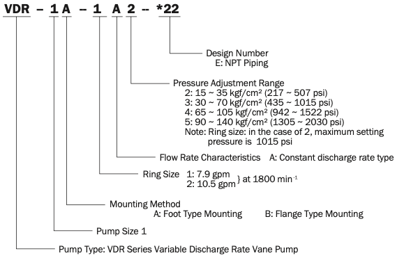
Understanding Model Numbers
Single Pump
Double Pump
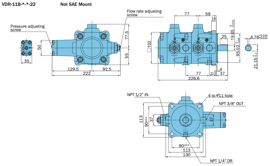
Installation Dimension Drawings
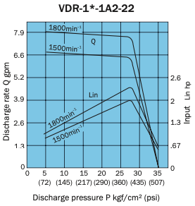
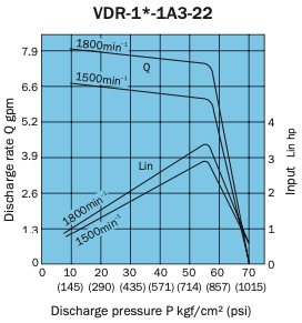
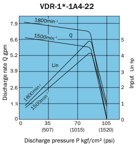
Performance Curves
Typical characteristics at hydraulic operating fluid kinematic viscosity of 32 centistokes.