SCI Sharp Controls: Phone: 704-394-1395 Fax: 704-392-5521Request a Quote!
Gas Amplifiers
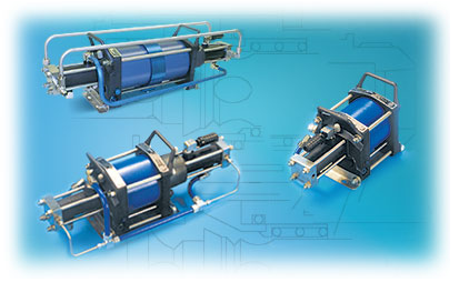
Air Driven Air Pressure Amplifiers
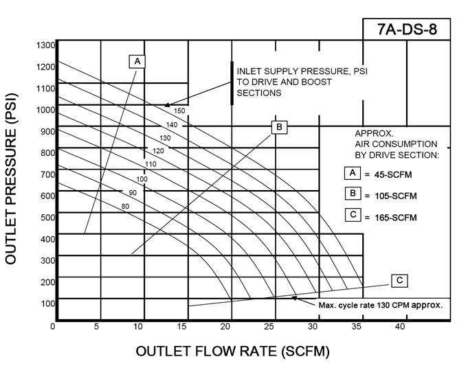
Hydraulics International air driven air pressure amplifiers operate using the principle of differential areas. Like any air tool,they operate from a single shop air connection for most applications. The air used for cycling exhausts through the muffler provided, or may be piped out of the area. The rest of the air is compressed to a higher pressure output. When output demand stops, the unit will stall in a force balanced condition consuming no power nor generating any heat. When output demand resumes, the unit automatically responds and cycles at the rate needed to meet that demand, up to the units capacity. Output Flow Reaches Maximum as the amplifier’s output pressure approaches the plant air input pressure. Output Flow Drops to Zero as the unit reaches theoretical stall. This value is estimated by multiplying input pressure x the last digit of the model number, e.g. model 5A-DS-5 with 100 PSI (6.9 BAR) plant air input will stall at approximately 500 PSI, model 5A-DS-2 at approximately 200 PSI (13.8 BAR). In practice however, controlling the maximum pressure desired is usually done with an external control.
Installation and Controls
Although there are a number of options for controlling these units, a final recommendation will be based on how the high pressure output air is to be used. Perhaps the most common type of control is that similar to a conventional air compressor:
Amplify the air into a receiver tank, ASME coded if permanently mounted.
Provide a safety relief valve at maximum rated tank pressure.
Provide a pressure switch* set to stop the air amplifier unit at about 95% of safety relief valve setting.
Provide an air or gas regulator (reducing valve) on the tank output set at the minimum usable amplified air pressure for the application.
* The pressure switch need not be electrical. Instead, the HII series of PCV valves performs this function in one simple unit with no electrical input required.
Features, Benefits & Applications
Typical Applications
Features, Benefits & Applications
Compact: installs off the floor, out of the way, in any position.
2 connections: plant air in, amplified air out. (Pilot air connection is optional for start-stop control with a PCV valve or solenoid valve and pressure switch.)
Can replace a dedicated air compressor: 10 HP size in a typical large plant spot requirement for 100 PSI when only 80 PSI is available. (Model 5A-DS-2)
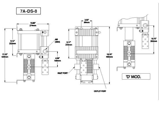
Replace bottled nitrogen: up to 700 PSI (48.3 BAR) for air testing, lab or production. (Model 5A-DS-5 & 7A-DS-8)